| Click to Run |
AP=Advanced Playtime (READ BELOW CAREFULLY)
- USE to MODEL and ANSWER Questions on AP EXAM
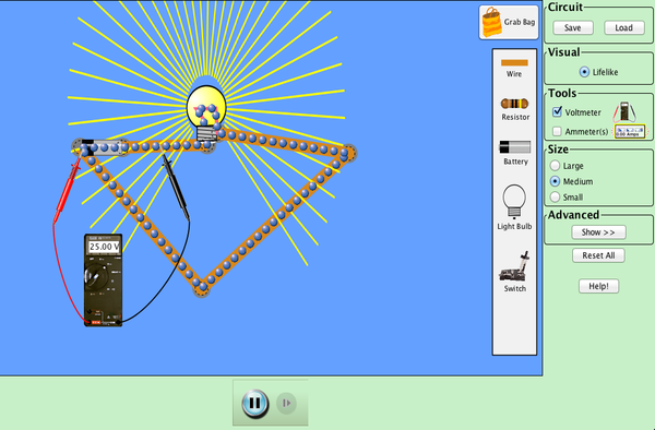
- Play with the Circuit simulator above.
- CREATE YOUR OWN CIRCUIT
- describe the construction of your circuit and values in a post DUE BY MONDAY MORNING)!!!)
- see if you can follow someone's recipe and get the same results
THIS IS A RESOURCE THAT I FOUND TO BE UNBELIEVABLY WELL WRITTEN
CLICK HERE
6. SEE PAGE 14 and COPY it VERBATUM into YOUR NOTES
AUTHOR:
Forrest M. Mims III, an amateur scientist and Rolex Award winner, is the most widely read electronics author in the world, and was named one of the “50 Best Brains in Science” by Discover magazine. His 60 books have sold over 7.5 million copies and have twice been honored for excellence by the Computer Press ...
http://goku17yenphysics.blogspot.com/2018/04/test.html
ReplyDeleteTest
Name- One Static Boi
ReplyDeleteGet 1 battery. Put one wire on the left side of the battery, and lengthen it a bit. Get a coin and connect one end to that previous wire. Get another wire and put it on the vacant side of the coin. Get 1 lightbulb and put it on that previous wire. Get 1 paperclip and put it on the open end of the lightbulb. Get one last wire and put it on the open end of the paperclip and attach the final end of the wire to the open side of the battery. And what do you know, your circuit is complete!!
Voltage- 10,000V
Current- 10A
Mods-
Put a resistor between the paperclip and the lightbulb, and the circuit with be extended.
Voltage- 5000V from the lightbulb to the lightbulb(ends)
10000V from lightbulb to resistor
Current- 5A
Have Fun!! :D
I constructed a series circuit starting off with a 9 volt battery connected to a coin by a wire, then that coin touches a row of three consecutive light bulbs with a resistance factor of 10 ohms each. Those three bulbs then are connected back to the original battery by another wire. The current of the system is .3 amperes and the voltage is 9 volts
ReplyDeletethis is christian pepe btw
DeleteI made a simple circuit that includes a battery, light bulb, and an on and off switch. 2 wires are connected to the ends of the battery. One end goes towards the light bulb white the other end goes top another wire and then to the on and off switch. The light bulb is connected to the on and off switch and then it runs though the circles to complete the circuit. My battery is at 9 volts white my light bulb is at 10 omega. As I increase the voltage on the battery, the current goes faster and the light bulb becomes brighter. As I decrease the voltage, the opposite happens. When I increase the ohms on the light bulb, the current goes slower and the light bulb becomes dimmer. When I decrease the ohms, the light bulb becomes brighter and the current becomes faster.
ReplyDeleteFiona Karol
ReplyDeleteLight bulb 1 is attached to a wire to its right and left. The wire on the right is attached to another wire pointing downwards. That consecutive wire is attached to a second light bulb. The second light bulb is attached to a short wire pointing downwards. A wire pointing towards the right is attached to it, and another wire pointing upwards is attached to a battery. The battery has a wire attached to the top of it, pointing to the left. Another wire goes upwards and another one connects to the upwards wire, pointing leftwards, going past the first light bulb. Another wire points downwards from the previous one. The final wire connects the first light bulb from its left side to the previous, downwards facing light bulb.
This is known as a series circuit, making it a closed circuit.
The current follows one path.
The current is the same in each light bulb and the total voltage is the sum of the voltages across each light bulb.
Light Bulbs (1 and 2): 10 Omegas
Battery (1): 9.0V
Please use the link (whether it allows you to click or copy and paste into the browser) for my response:
ReplyDeletehttps://docs.google.com/document/d/16gLae0Bif2SU3CWzW4cxpOVL3S7NRqiH1FOaubNKzn4/edit?usp=sharing
I created a parallel circuit which is powered by a 9 volt battery. The battery is connected to a paper clip and a coin on either side. From there two wires stretch downward until they reach the middle of the circuit. Two more wires are attached to either end of the previous wires and form a closed circuit with a lightbulb as the link in the middle. The resistance of the lightbulb is 10 ohms. From the ends of the last two wires, two more stretch down a little farther and are connected with two more wires and another lightbulb reading a resistance of 10 ohms in the center. The resulting shape is a rectangle and the resulting circuit is a parallel one. As you adjust the voltage of the battery higher the lightbulbs become significantly brighter but the resistance stays the same. As you increase the resistance in a lightbulb the bulbs becomes dimmer.
ReplyDeleteThis comment has been removed by the author.
ReplyDeletehttps://docs.google.com/document/d/10NJMRjZjLWXcGGVDR8Q_RzqtWBcAw6M2yhX5yPR9lug/edit?usp=sharing
ReplyDeleteAll info on above link, pls copy and paste into search bar!
(Format credit to Seena)
I created a parallel circuit with a nine volt battery, two light bulbs, and a resistor. The whole structure resembles a rectangle with a line running down the middle. There is on light bulb on one side, one in the middle, and then on the opposing side to the first bulb is the battery and resistor. Both light bulbs have 10 ohmns and the resistor has 1.5 ohmns. I noticed as I increased the power of the battery, the hotter the battery got and over heated the circuit. I also noticed that the flow of electrons is slower and more concentrated at the light bulb that is furthest from the battery, as the light bulb in the middle has a faster, and less condensed electron flow. Also as I increase the power on the resistor, the slower the circuit flows.
ReplyDelete